This guide will walk you through each individual step required to ensure a seamless 1NCE SIM installation process. From preparing the necessary tools and equipment to understanding the SIM card specifications, you will be equipped with all the knowledge needed to get started.
Rework SOP
Step 1:
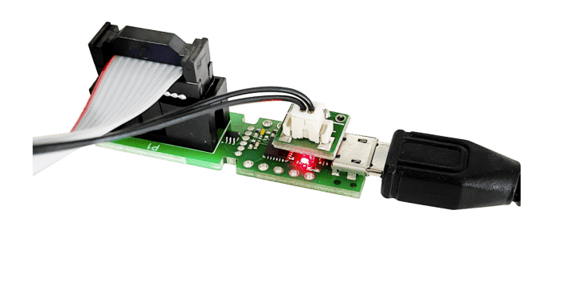
You will need the tools and the Provisioning Cable assembly from Superfy for this
rework.
Tools: Torque driver, 3 mm Hex, PH2, PH1, Tag-Connect, power to USB interface cable, magnet.
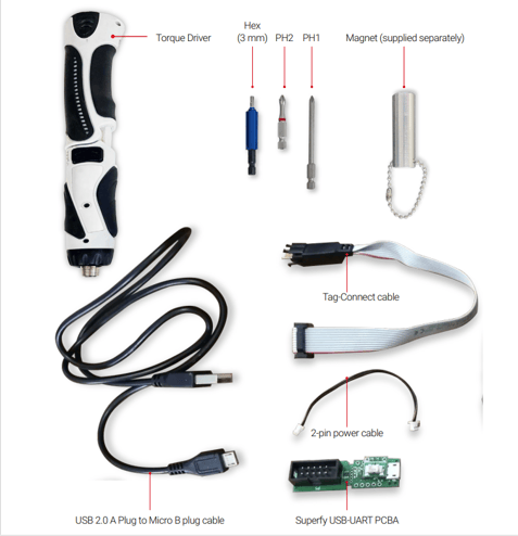
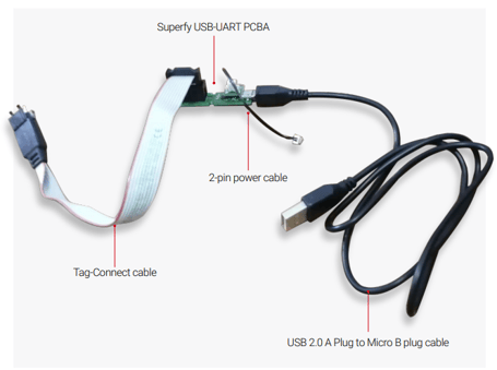
FW Flash Cable Parts Assembly
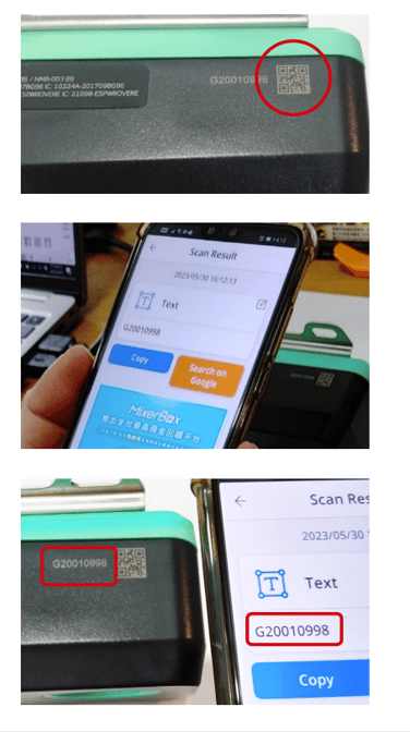
Scan QR Code
Step 2:
A. Scan the QR code of the serial number (S/N) on the enclosure with a QR code scanner or a smart phone.
B. Make sure the scanner or the phone scans the same S/N as the one beside the QR code
C. Record the S/N
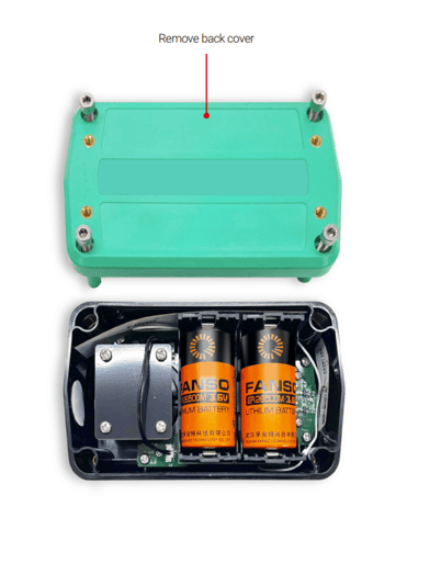
Disassembly
Step 3:
Remove the back cover. Ensure that the screws are kept within their respective hole
in the lid as there are two different lengths. (When re-assembling the back cover, torque screws to 7~7.5 kgf.cm)
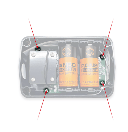
Step 4:
Remove the 4 larger self-tapping screws. (When re-assembling, torque screws to
2 kgf.cm).
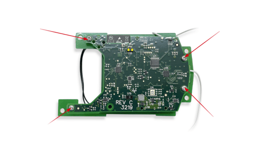
Step 5:
Remove 4 x small machine screws screws (When re-assembling, torque screws
to 2 kgf.cm).
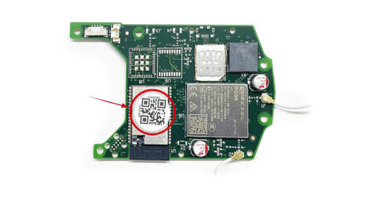
Step 6:
Read this QR code (EUI-64) on the PCBA to record the rework unit.
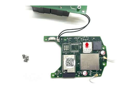
Swap SIM
Step 7:
Remove or replace SIM as required. Make sure the SIM card you are going to install is
a Micro SIM card.
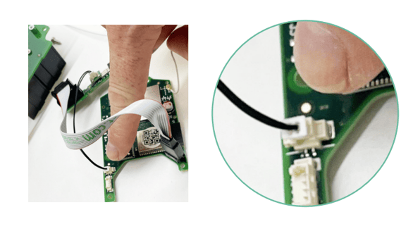
Step 8:
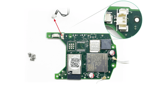
Disconnect the battery power lead.
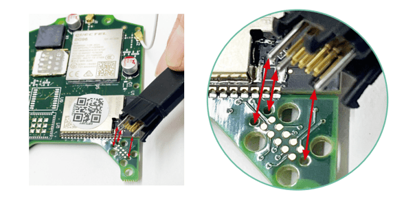
Connect Tag-Connect
Step 9: Connect Tag-Connect plug-of-nails interface. You may need to gently squeeze the
black plastic area around the pins to fit the connector into the outer four retaining
holes.
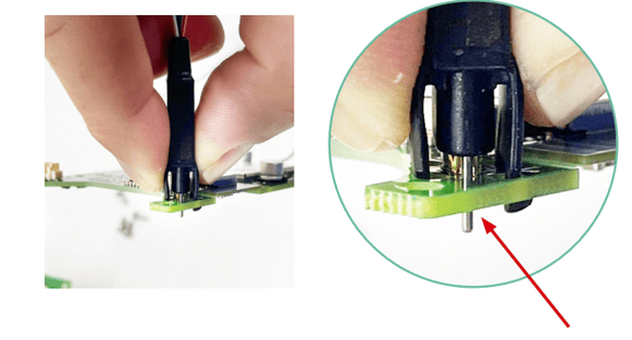
Step 10:
Check Tag-Connect is fully inserted and retained. The black plastic legs will be acting
as retaining clips against the bottom of the PCB.
Plug Power Cable to PCBA
Step 11:
Plug power cable to PCBA from the provisioning cable.
Step 12:
Plug the USB cable into the PC and confirm that the red power LED on the
programming cable is lit.
Device Firmware
Pre-Requisites
You may need to install the drivers for the USB-to-serial converter used in the programming cable if this is your first time using this cable on your PC. The drivers can be found here:
https://www.silabs.com/developers/usb-to-uart-bridge-vcp-drivers?tab=downloads
This process highlights how to install a specific version firmware on the device. If you do not select a specific version, by default the latest version will be used.
Steps for Device Firmware Upgrade
A. Equipment:
1. PC running the latest version of Chrome.
2. PC having CP210x driver installed. Go to CP210x USB to UART Bridge VCP Drivers -
Silicon Labs (silabs.com), download the CP210x driver according to the OS on your
PC, and install it.
2.1: After you have the CP210x driver downloaded from the link above. Go to Device
Manager on your computer and click Other devices, then right click the driver
shown and click Update Drivers.
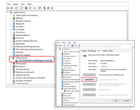
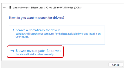
2.2: Click Browse my computer for drivers
2.3: Find the CP210x folder on your computer, click the folder and press Ok,
Then press Next.
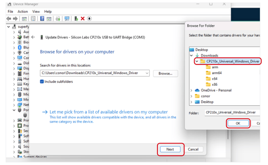
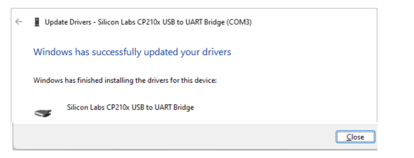
2.4: Installing new driver is complete
3. A G2 device PCB with the correct SIM card inserted, the Tag-Connect and power cables
attached, and the USB connector plugged into the PC.
B. Flashing Firmware
1. Log in to the Superfy platform using the username/email and password provided by Superfy.

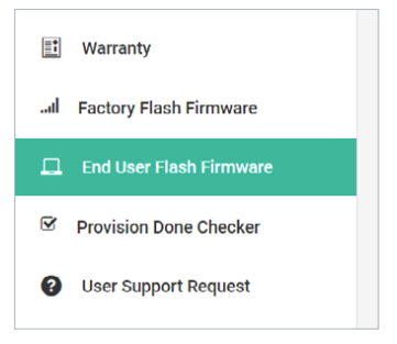
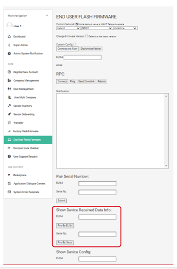
2. Navigate to the Device Firmware section of the platform using the navigation area on
the left side of the page.
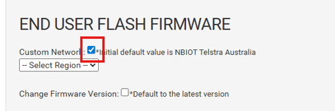
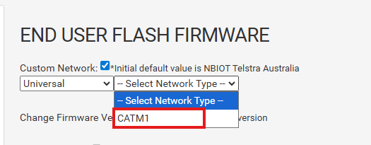
3. Click on the Custom Network checkbox at the top of the page.
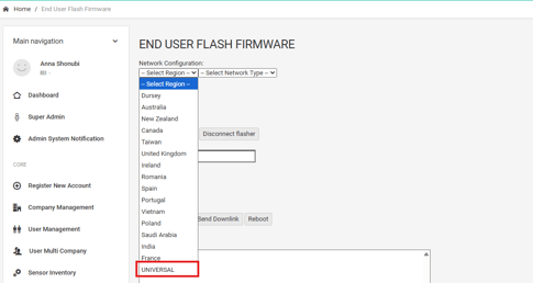
4. Select Universal from the Select Region dropdown list.
5. Select CATM1 from the Select Network Type dropdown list.
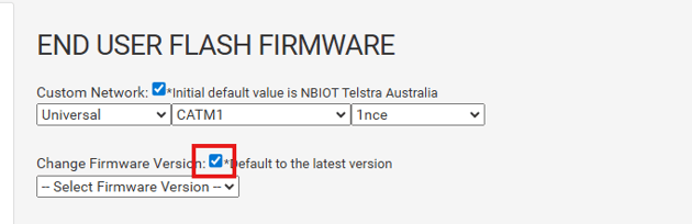
6. Select 1NCE from the Select Carrier dropdown list.

7. Click on the Change Firmware Version checkbox.
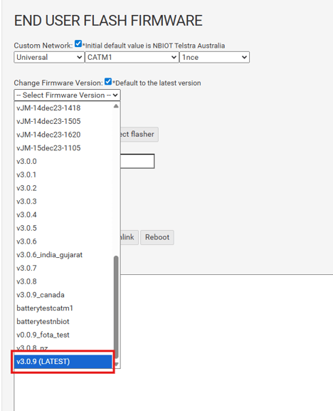
8. Select V3.0.9 (LATEST) from the Select Firmware Version dropdown list.
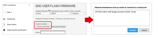
9. Click on the Connect and Flash button and you will see a popup window listing one
or several ports available on your PC, see the 2nd image below. Choose the CP2102N
USB to UART Bridge Controller and click on Connect button.
10. Wait for the process to end. It should look like the following:
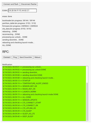
Note: the exact contents will vary depending on particular firmware versions
11. To check and confirm the data is received on the dashboard platform.
-
-
- Scroll down to Show Device Received Data Info:
- Put S/N or EUI64 code and click Find button. A row of data with related information will show.
- Check Last_received timestamp field, it shows the latest timestamp that the data is received by the platform from the sensor.
- The timestamp is in UTC. The screen capture below is for reference
-
At this point the firmware has been flashed and the sensor can be put back together by
following the steps in the Disassembly of Smart Sensor section in reverse order.
Note: If the provisioning process fails, you will see the log area turn RED.
If possible, the device will then reboot and retry the connection process again.
Under some circumstances with new SIM cards the device may fail initially and
then work the second time due to a SIM card activation delay.
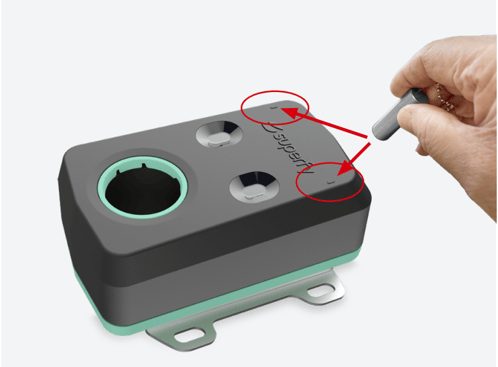
Step 13:
When the sensors are re-assembled, take the magnet provided and hold it close to either of the two areas circled in red below. Make sure you hear 5 beeps from the sensor to ensure it is turned off before removing the magnet.
Please note that the device will not react to the magnet if it is currently measuring or sending data
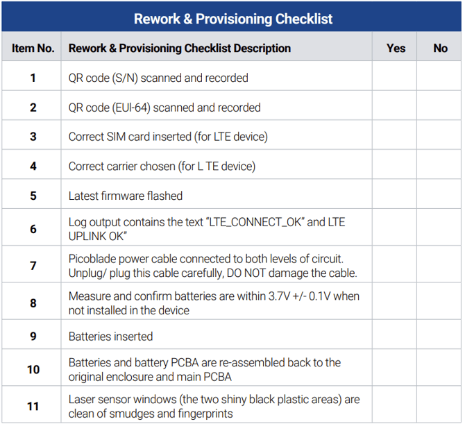
Checklist
Download the hardcopy of this manual Here